

DAS Design & Engineering
Engineering Connectivity
for Complex & Critical
Environments
From Requirement → To Verified Network
02 — Model
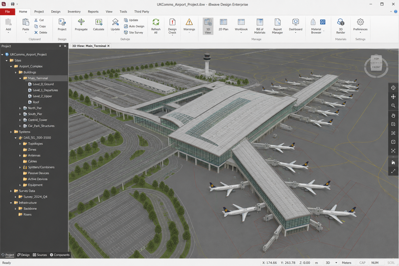
Before Anything Is Installed,
We Build the Network Virtually.
Architecture · Materials · RF Environment · Operational Constraints
03 — Engineering Inputs
The Model Is Only As Good
As The Engineering Behind It.
Before RF performance can be engineered, the physical environment must be understood. Building geometry, construction materials, operational requirements and installation constraints are translated into a virtual RF model of the built environment.
Building Geometry
Floor plans, elevations, ceiling heights, risers, cores and spatial relationships establish the physical environment.
Materials & Attenuation
Walls, glazing, concrete, partitions and structural elements are characterised to understand their influence on RF propagation.
Operational Requirements
Coverage objectives, critical areas, user environments and operational priorities define what the network needs to achieve.
Engineering Constraints
Equipment locations, cable routes, power, fibre, access, maintainability and installation restrictions influence the design from the outset.
We model the environment to understand how RF will behave within it.
04 — Design Survey
Good Design Starts
With Understanding the Environment.
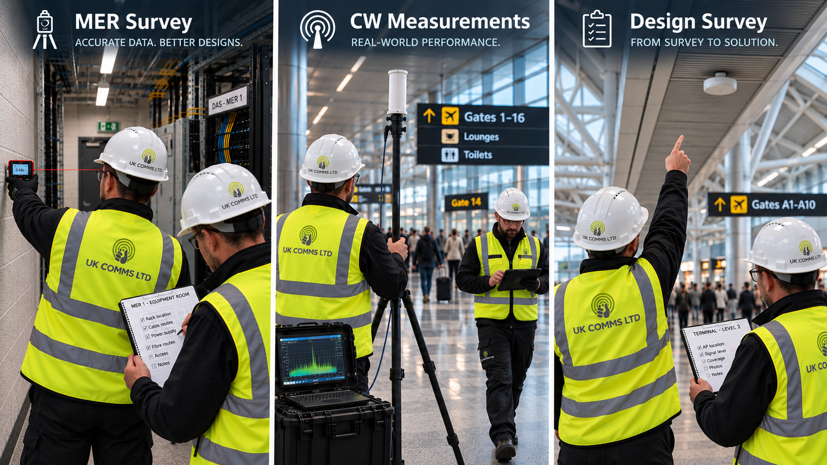
Before modelling begins, the physical environment, RF conditions and infrastructure constraints must be understood.
Building & Infrastructure
Understanding construction, ceiling types and heights, materials, risers, equipment rooms, containment, power, fibre and potential cable routes.
RF Environment
CW measurements and RF survey activity establish how signals behave within the real building environment and provide measured inputs to support the design process.
Access & Constructability
Identifying equipment locations, antenna positions, access restrictions, working constraints and installation considerations before they become problems during construction.
Survey Record
Dimensions, photographs, measurements, drawings and site observations are captured to provide a controlled engineering reference for the subsequent design.
What we learn on site
defines what we engineer in the model.
05 — RF Engineering
Every Antenna Has a Reason to Be There.
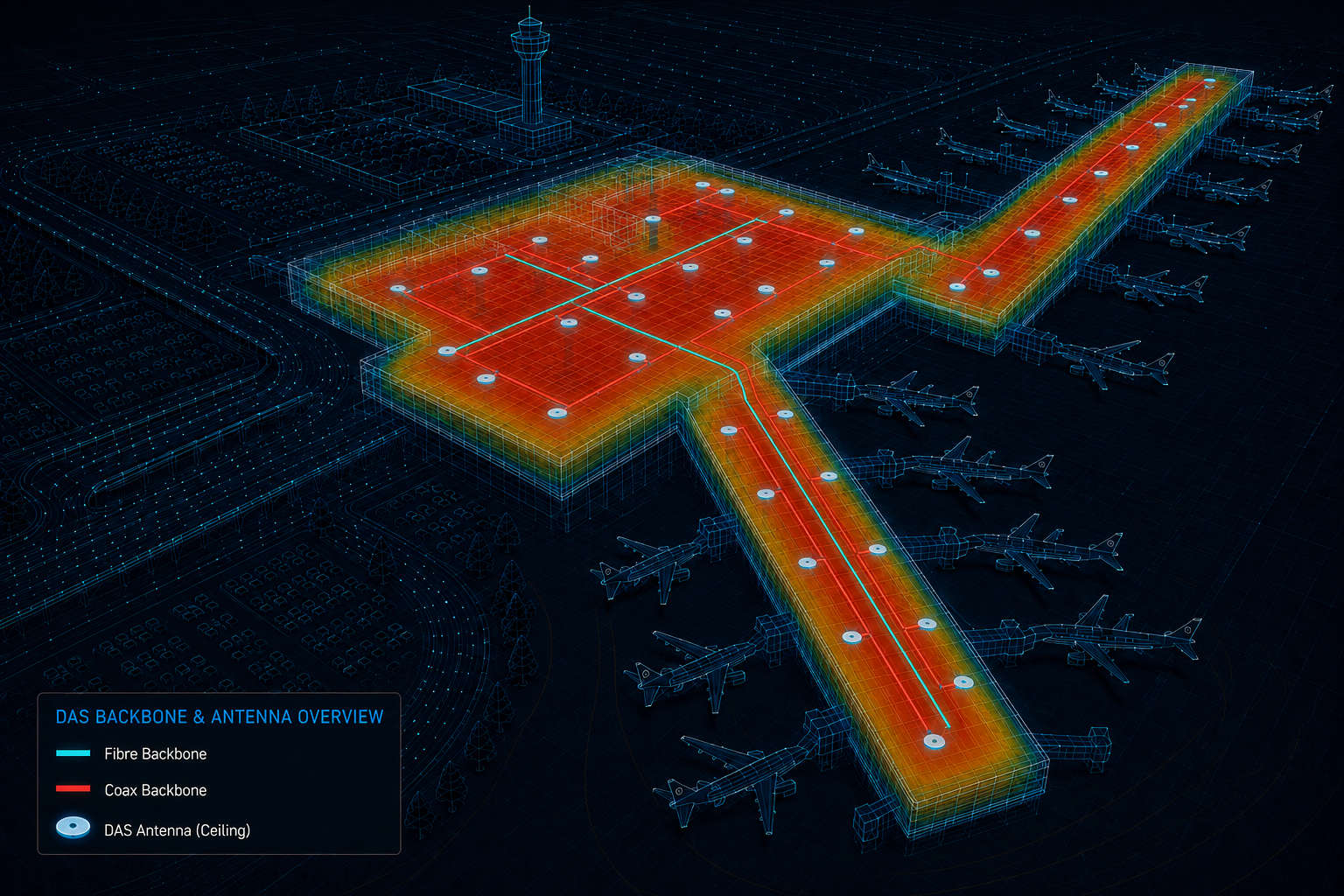
Antenna placement is not simply about filling a building with signal. Each location is engineered against the RF objectives, physical environment, network architecture and operational requirements of the space it serves.
Coverage
Engineering sufficient signal throughout the required service areas.
Capacity
Designing for where users are, how spaces are used and where network demand is concentrated.
Dominance
Controlling the intended serving signal and limiting unwanted overlap between coverage areas.
Interference
Managing RF interaction between antennas, sectors, technologies and the surrounding radio environment.
MIMO
Maintaining appropriate antenna strategy, separation and RF paths where multi-stream performance is required.
Resilience
Considering architecture, equipment distribution and critical service requirements as part of the overall design.
Prediction informs the design.
Engineering judgement shapes the network.
06 — Detailed Design & JOTS
From Engineered Solution
to Construction-Ready Design.
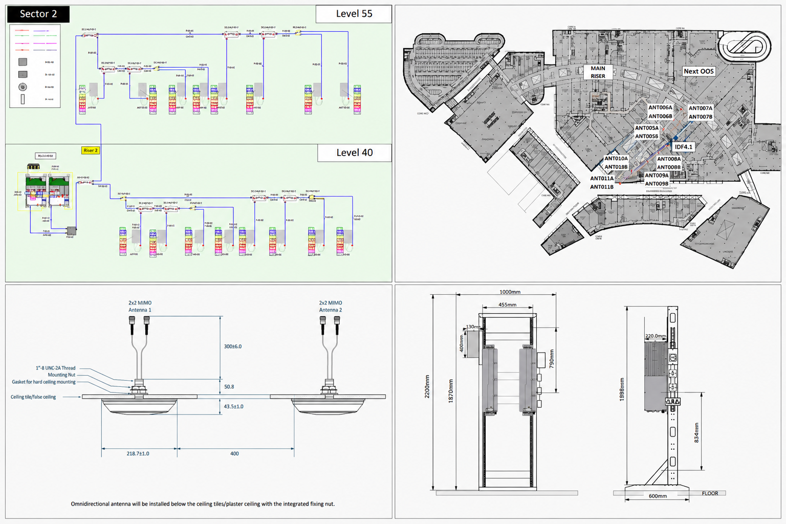
The engineered RF solution is developed into the coordinated drawings, schematics, schedules and installation details required to take the system from design into construction.
Design Drawings
Detailed floor plans define antenna locations, equipment positions, cable routes, containment interfaces and system connectivity.
System Schematics
RF architecture is documented from source and distribution equipment through to the final antenna network.
Equipment & Installation Details
Equipment layouts, mounting arrangements and antenna installation details define how the engineered solution is physically implemented.
Schedules & Design Information
Cable schedules, equipment schedules, labelling and supporting design information provide a coordinated package for construction.
The RF model defines the solution.
The JOTS design pack defines how it is delivered.
07 — Buildability & Installation
A Design Is Only Successful
If It Can Be Built.
RF performance is only part of the engineering challenge. Equipment locations, cable routes, containment, access, structural constraints and installation methodology must all be considered before the design reaches site.
Routing & Containment
Cable routes are engineered around the real building — existing services, containment, fire compartments and physical access.
Equipment Location
Remote units, passive components and antennas are positioned with installation, maintenance, power, fibre and accessibility in mind.
Access & Coordination
Ceiling access, working-at-height requirements, operational restrictions and interfaces with other trades are considered during design.
Installation Detail
Drawings, cable schedules, equipment schedules and installation information translate the RF design into a controlled construction package.
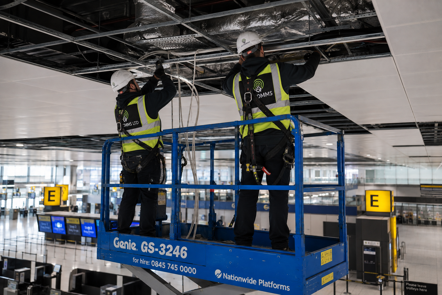
We don't design in isolation.
We design for the real environment.
08 — Commissioning
Installed Is Not
the Same as Operational.
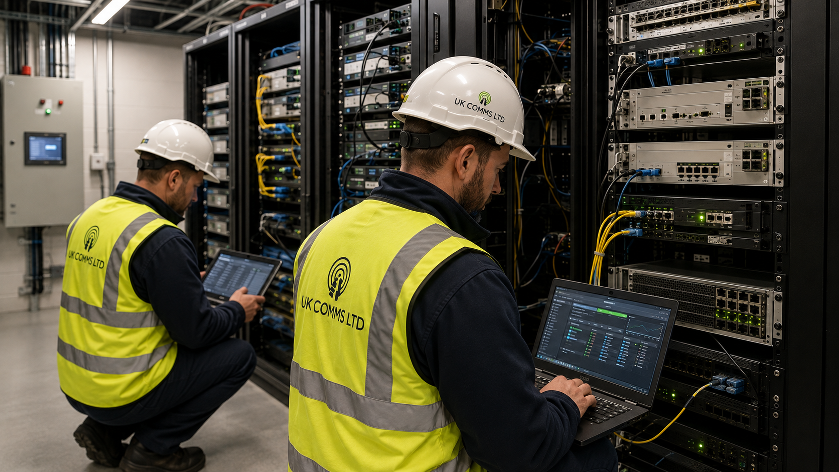
Installation completes the physical network. Commissioning brings the system into service — validating connectivity, configuration, system operation and performance against the approved design.
System Integrity
Confirming equipment status, fibre connectivity, RF paths, alarms and system communications across the installed DAS.
Configuration & Integration
Commissioning active equipment, validating system configuration and confirming correct integration across the network architecture.
RF System Performance
Checking system levels, gain, losses and RF performance against the approved design parameters and commissioning requirements.
Commissioning Records
Recording equipment status, configuration, test results, alarms and commissioning evidence as part of the controlled handover process.
We don't assume the system performs.
We prove it.
09 — Walk Testing & Verification
The Network Isn't Finished
Until It's Proven.
Walk testing provides the measured evidence required to validate the installed network against the design intent — before integration, after integration and through final optimisation.
Pre-Integration Testing
Establishing the existing RF environment and confirming baseline conditions before the DAS is brought into service.
Post-Integration Verification
Measuring the live network following integration to confirm coverage and RF performance throughout the designed environment.
Analysis & Optimisation
Walk-test results are analysed against the design intent, identifying areas requiring adjustment, investigation or optimisation.
Evidence & Handover
Final survey data provides a documented record of network performance and supports technical acceptance and handover.
Prediction tells us what should happen.
Measurement proves what actually happened.
10 — As-Built Documentation
The Final Record of
What Was Actually Delivered.
Installation rarely finishes exactly as it began on the drawing.
Site changes, final equipment locations, cable routing and test results are reconciled into the project record to create an accurate representation of the completed system.
Site Reconciliation
Installation changes and site variations are captured, reviewed and incorporated into the final project record.
Final Installation Record
Final antenna locations, RF components, equipment positions and cable routes are documented to reflect the installed network.
Test & Commissioning Evidence
VSWR, DTF and relevant commissioning records provide supporting evidence of the completed RF infrastructure.
Controlled As-Built Package
Drawings, records, schedules, photographs and supporting engineering information are consolidated into the final controlled documentation set.
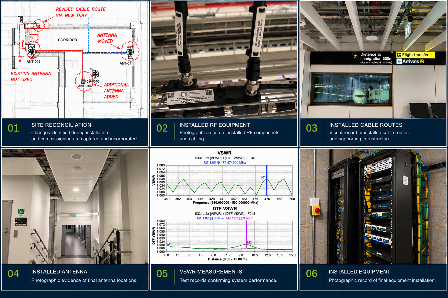
The design shows what should be built.
The as-built pack records what actually exists.
11 — System Support
Performance Doesn't End
at Handover.
A DAS is an operational system, not simply an installed asset. UK Comms supports fault investigation, alarm diagnosis and system troubleshooting — using system monitoring, commissioning records and engineering knowledge to identify issues and restore the network to its intended operational state.
Alarm Diagnosis
System alarms and event logs provide the starting point for identifying faults and abnormal operating conditions.
Fault Investigation
Engineering knowledge of the DAS architecture allows faults to be traced through active equipment, fibre, RF distribution and associated interfaces.
Rectification
Issues are investigated methodically, corrective action is implemented and the affected system elements are returned to their intended operational condition.
Close-Out
Following rectification, alarm status and system operation are checked to confirm the fault has been successfully cleared.
Finding the alarm is only the beginning.
Understanding why it happened is the engineering.
12 — Network Architecture
Different Environments.
Different Network Strategies.
Dedicated Infrastructure
A DAS engineered around the requirements of a single mobile network operator.
- Operator-specific requirements
- Dedicated system architecture
- Coverage & capacity engineered to the environment
Shared Infrastructure
Multiple operator services integrated into a common DAS infrastructure, providing shared coverage across complex environments.
- Multiple operator inputs
- Shared DAS infrastructure
- Common in-building antenna network
- Capacity, coverage & integration engineered collectively
The architecture may change.
The engineering discipline doesn't.

13 — PMR & Emergency Communications
When Communication
Is Mission-Critical,
Coverage Cannot Be Optional.
Critical communications require reliable radio coverage across the environments where operational teams need to work.
Operational Coverage
Designing radio coverage around the areas, users and operational requirements of the environment.
Critical Environments
Engineering coverage across terminals, back-of-house areas, plant rooms, service corridors, stairwells and other challenging spaces.
System Engineering
RF modelling, antenna strategy, system architecture and detailed design developed around the required radio service.
Verification
Coverage is measured and verified against the defined design requirements following installation and commissioning.
The network is infrastructure.
The communication it enables is operationally critical.

14 — Engineered Certainty
From Requirement.
To Reality.
To Verified Performance.
From survey and RF modelling through detailed design, installation support, commissioning and verification — UK Comms provides the engineering discipline that turns connectivity requirements into buildable, operational networks.
iBwave is the tool.
Engineering judgement is the capability.